Oil Exploration with LTspice

Explorative oil drilling involves measuring rock formation resistivity. Below 300 meters, the solid rock is saturated with fluid water and that water is conductive salt water. But since salts don't dissolve in oil, wherever trapped hydrocarbons displace the salt water, the rock is resistive. Resistivity measurement has been the main means of identifying hydrocarbon bearing rock in wells for about eighty years.
But there's a hitch. Drilling a well involves introducing dense, conductive muds and fluids to the hole to weigh down the drilling column to a density that approaches the rock so that the natural formation fluids don't squirt out of the well in a blowout that is both dangerous to the rig crew and intolerable to the environment. So the resistance of the natural rock must be measured in a manner that looks beyond the foreign conductive additions to the drill column.
The primary method of measuring formation resistivity while ignoring the conductivity of the borehole is to use coils that excite and detect eddy currents in the formation. These can be designed and operated to be sensitive to the eddy currents that extend several feet into the formation, well beyond the borehole. Considering the size of the oil industry, I'm sure it's needless to say that there is fierce competition in the development of instrumentation that can find oil and I'm not wasting your time with a worthless quiz question.
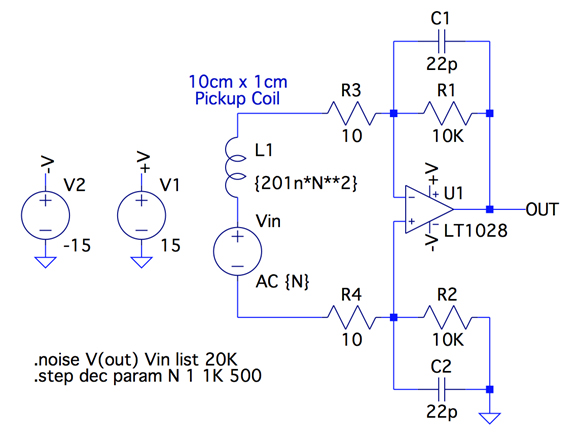
Figure 1 shows a practical preamp for the pickup coil as has been used in oil exploration. L1 is the antenna pickup coil that senses eddy currents in the formation. The value is given as 201n*N**2, i.e., 201 nanohenry times the number of turns, N, squared. That's the nominal inductance of a 10cm by 1cm antenna that can comfortably fit in an oil well and was obtained by numerically integrating the elliptical integral.

Now the question: How many turns should the antenna coil have for best Signal to Noise Ratio at 20kHz? The issues that come into play are
1. The signal increases as the number of turns so you want as many turns as possible.
2. The inductance increases as the number of turns squared. This both reduces that gain at frequency and also increases the noise as the LT1028's current noise is readout by the input impedance, so you want as few turns as possible.
OK let's use LTspice to solve this problem. The main advantage of LTspice here is that opamp noise is modeled correctly so it is possible to find the answer through simulation. We simply do a noise simulation and plot the signal to noise ratio versus the number of turns and pick the number of turns that gives the highest signal to noise. This is particularly easy in LTspice because it allows you to do a noise simulation at fixed frequency while sweeping another parameter, i.e., the turns N.
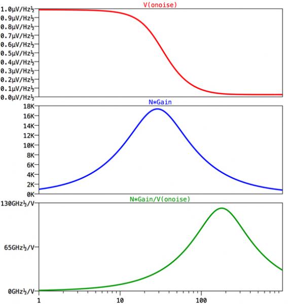
Since the signal is proportional to the number of turns, the output signal is simply N*Gain for a unit input signal. The signal to noise ratio is then N*Gain/V(onoise) for a unit input signal. Since many people prefer to do discuss noise input-referenced, one can equivalently plot N/V(inoise) to the identical effect.
Figure 2 shows the output referenced noise in the top plot pane, the output signal for a unit input signal in the middle pane, and the signal to noise for a unit input signal in the bottom pane.

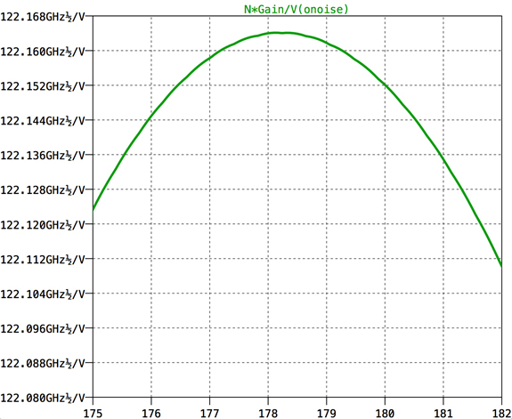
Figure 3 shows that signal to noise zoomed in so one can identify the optimum number of turns. And the answer is that you're going to find the most oil in your oil well if you wind your pick-up coil with 178 turns. There, the signal to noise is 1.2216e11 for eddy currents that induce 1 Volt per turn in the pick up coil. Since there are 178 turns, this design will yield a signal to noise of 100 when the eddy currents induce 4.6pV per turn.


